

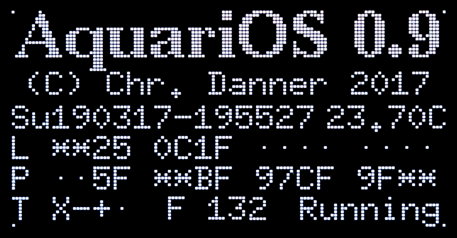
 AquariOS - Aquarium Operating System
AquariOS - Aquarium Operating System
AquariOS - Aquarium Operating System

 Introduction
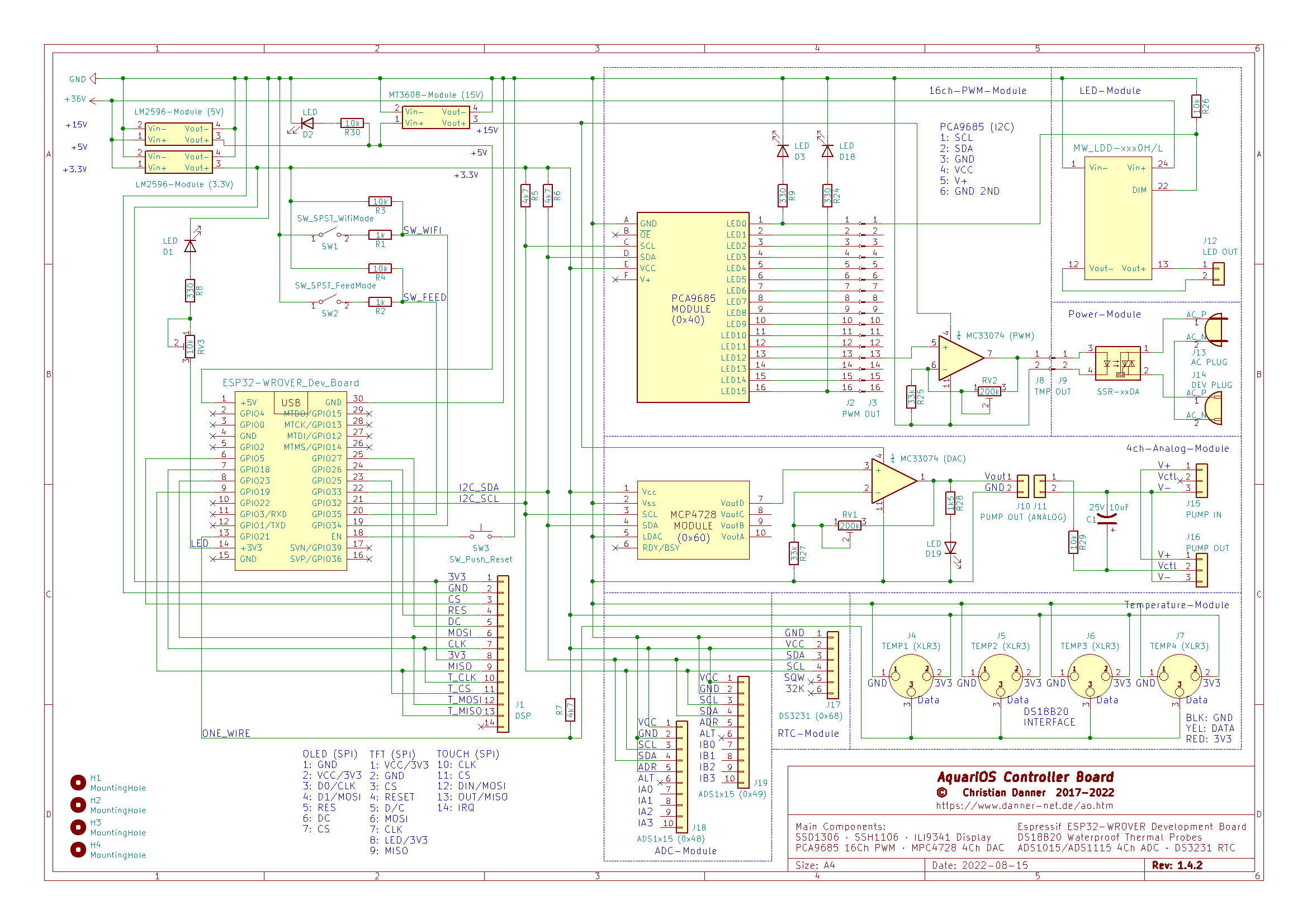
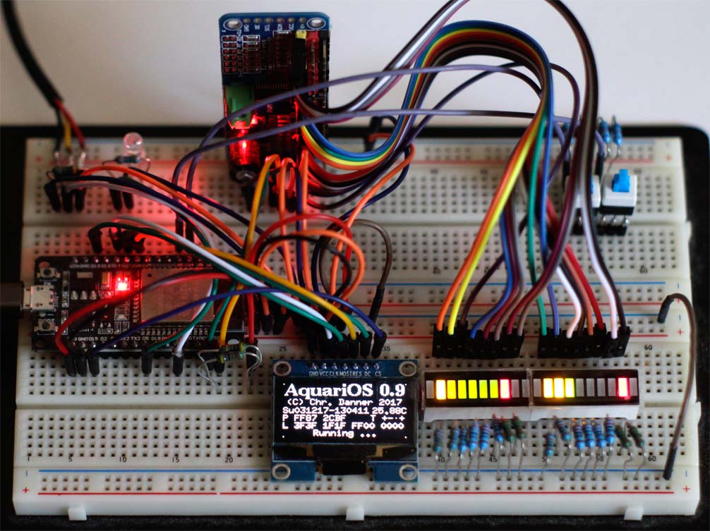
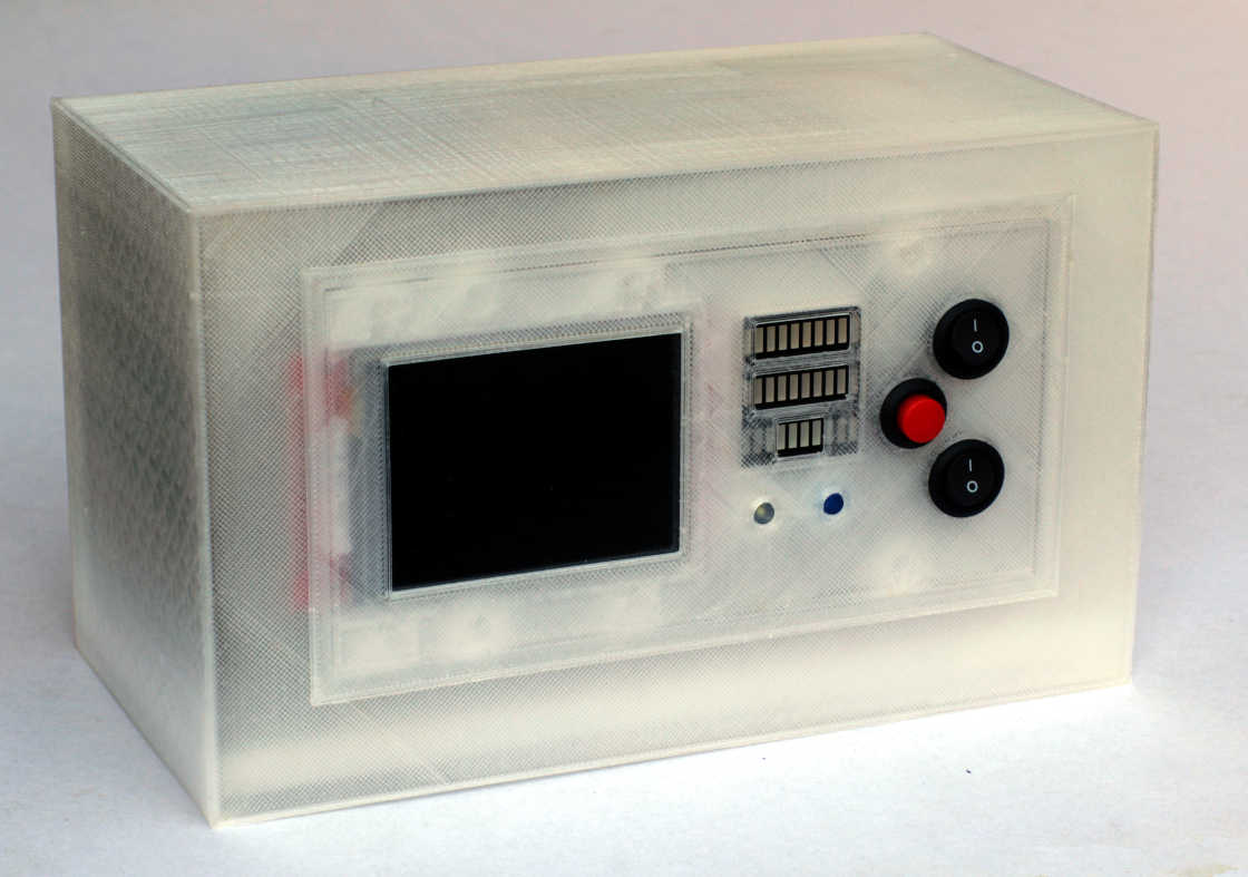
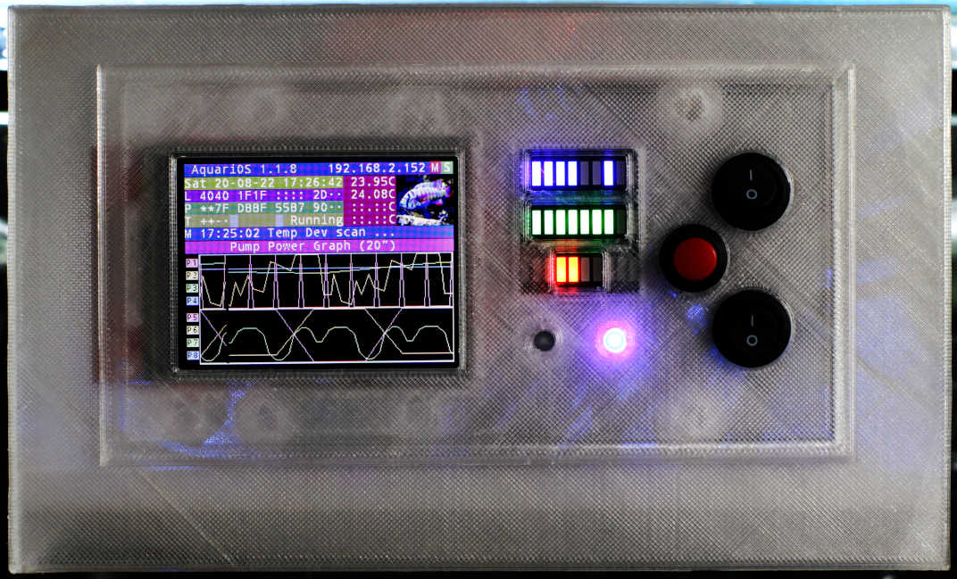
 Hardware
| Shopping List | ||
|---|---|---|
| 4 x | 400 Point Mini Solderless Breadboard 3.35" x 2.16" | USD 4.20 |
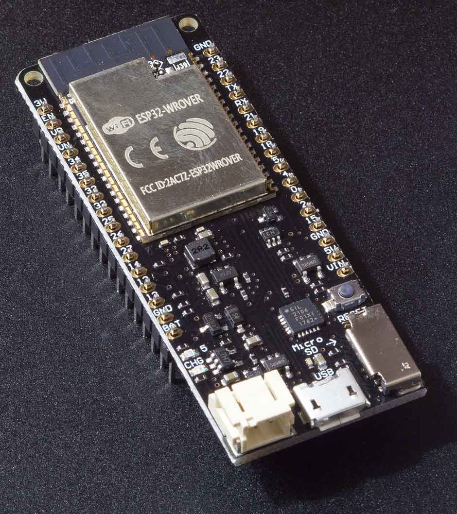
| 1 x | Espressif Systems ESP32 WROVER Development Board | USD 9.75 |
| 2 x | LED-10-Segment-Bargraph-Display Fixed Tricolor B10RYG | USD 8.00 (5 pcs) |
| 1 x |
SSD1306 / SSH1106 SPI 128X64 OLED Display Module
or ILI9341 (XPT2046) SPI 240X320 TFT (Touch) Display Module |
USD 5.50
or USD 6.50 |
| 1 x | DS18B20 Waterproof 1-Wire Thermal Probe | USD 2.00 |
| 1 x | DS3231 RTC I²C Module with CR2032 Battery | USD 3.00 |
| 1 x | PCA9685 16-Channel 12-Bit PWM I²C Module | USD 2.30 |
| 1 x | MCP4728 4-Channel 12-Bit DAC I²C Breakout Module | USD 7.00 |
| 2 x |
ADS1015 4-Channel 12-Bit ADC I²C Breakout Module
or ADS1115 4-Channel 16-Bit ADC I²C Breakout Module |
USD 7.00
or USD 8.00 |
| 2 x | MC33074PG OP-AMP 14DIP | USD 8.20 |
| 1 x | LM2596 3A DC-DC Step Down Power Module | USD 1.20 |
| 1 x | MT3608 2A DC-DC Step Up Power Module | USD 0.80 |
| Manufacturer | Type | Mode | Voltage |
|---|---|---|---|
| Jebao / Jecod |
WP pumps DC pumps |
DC | 0 .. 5 V |
|
SW pumps Coral Box DCA pumps |
DC | 0 .. 10 V | |
| Maxspect / IceCap | IceCap Gyre Interface Module | DC | 0 .. 10 V |
| Reef Octopus | VarioS, Pulse 2, Pulse 4 | DC | 0 .. 10 V |
| Sicce | XStream-E | DC | 0 .. 10 V |
| Speedwave | DC pumps | DC | 0 .. 5 V |
| Tunze |
Turbelle Nanostream Electronic 6040, 6055, 6095 Turbelle Stream Electronic 6105, 6155, 6255, 6150 (Stream 3/3+) |
DC | 0 .. 10 V |
| Waveline |
DC6000, DC12000, DC20000 WavePuck, WavePuck II |
DC | 0 .. 10 V |
 Firmware
ets Jun  8 2016 00:22:57

rst:0x1 (POWERON_RESET),boot:0x13 (SPI_FAST_FLASH_BOOT)
configsip: 0, SPIWP:0xee
clk_drv:0x00,q_drv:0x00,d_drv:0x00,cs0_drv:0x00,hd_drv:0x00,wp_drv:0x00
mode:DIO, clock div:1
load:0x3fff0018,len:4
load:0x3fff001c,len:1324
load:0x40078000,len:7788
ho 0 tail 12 room 4
load:0x40080400,len:6448
entry 0x400806e8
scan start
scan done
5 networks found
1: Edelweiss (-61)*
2: Vodafone Hotspot (-85)
3: Vodafone Homespot (-85)
4: KabelBox-985B (-86)*
5: EZCast2-C9A2E7F6 (-94)*

Initializing SD card...initialization failed!
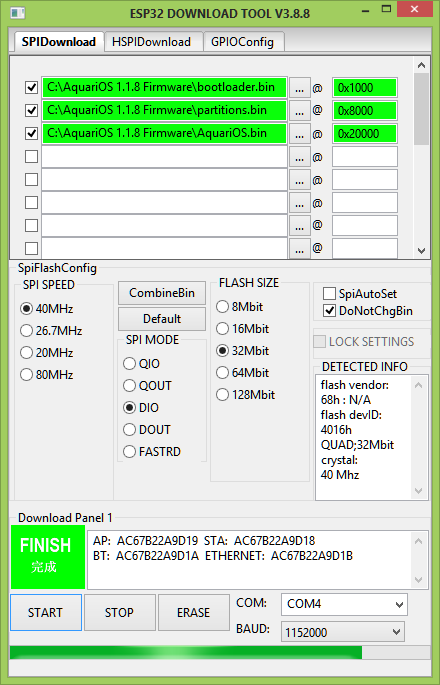
*************************** START ****************************

test offset :  4096 0x1000
case ok
test offset :  32768 0x8000
case ok
test offset :  131072 0x20000
case ok
.
Uploading stub...
Running stub...
Stub running...
FLASH_CRYPT_CNT 0
ABS_DONE_0 False

*************************** END ****************************


*************************** START ****************************

test offset :  4096 0x1000
case ok
test offset :  32768 0x8000
case ok
test offset :  131072 0x20000
case ok
......
Uploading stub...
Running stub...
Stub running...
FLASH_CRYPT_CNT 0
ABS_DONE_0 False
Compressed 25728 bytes to 15797...
Compressed 3072 bytes to 106...
Compressed 1323184 bytes to 783044...

 is stub and send flash finish

*************************** END ****************************
ets Jun  8 2016 00:22:57

rst:0x1 (POWERON_RESET),boot:0x3f (SPI_FAST_FLASH_BOOT)
configsip: 0, SPIWP:0xee
clk_drv:0x00,q_drv:0x00,d_drv:0x00,cs0_drv:0x00,hd_drv:0x00,wp_drv:0x00
mode:DIO, clock div:2
load:0x3fff0030,len:7056
load:0x40078000,len:14832
load:0x40080400,len:3748
entry 0x40080678
I (27) boot: ESP-IDF v4.3-dirty 2nd stage bootloader
I (27) boot: compile time 19:50:59
I (27) boot: chip revision: 1
I (60) boot.esp32: SPI Speed      : 40MHz
I (60) boot.esp32: SPI Mode       : DIO
I (60) boot.esp32: SPI Flash Size : 4MB
I (62) boot: Enabling RNG early entropy source...
I (68) boot: Partition Table:
I (71) boot: ## Label            Usage          Type ST Offset   Length
I (79) boot:  0 nvs              WiFi data        01 02 00009000 00016000
I (86) boot:  1 phy_init         RF data          01 01 0001f000 00001000
I (93) boot:  2 factory          factory app      00 00 00020000 001e0000
I (101) boot: End of partition table
I (105) esp_image: segment 0: paddr=00020020 vaddr=3f400020 size=55a9ch (350876) map
I (257) esp_image: segment 1: paddr=00075ac4 vaddr=3ffb0000 size=08698h ( 34456) load
I (273) esp_image: segment 2: paddr=0007e164 vaddr=40080000 size=01eb4h (  7860) load
I (277) esp_image: segment 3: paddr=00080020 vaddr=400d0020 size=c6a4ch (813644) map
I (612) esp_image: segment 4: paddr=00146a74 vaddr=40081eb4 size=1c5f4h (116212) load
I (672) esp_image: segment 5: paddr=00163070 vaddr=50000000 size=00010h (    16) load
I (697) boot: Loaded app from partition at offset 0x20000
I (697) boot: Disabling RNG early entropy source...
I (709) psram: This chip is ESP32-D0WD
I (709) spiram: Found 32MBit SPI RAM device
I (709) spiram: SPI RAM mode: flash 40m sram 40m
I (714) spiram: PSRAM initialized, cache is in low/high (2-core) mode.
I (721) cpu_start: Pro cpu up.
I (725) cpu_start: Starting app cpu, entry point is 0x400818e0
I (0) cpu_start: App cpu up.
I (1618) spiram: SPI SRAM memory test OK
I (1626) cpu_start: Pro cpu start user code
I (1626) cpu_start: cpu freq: 160000000
I (1626) cpu_start: Application information:
I (1629) cpu_start: Project name:     AquariOS
I (1634) cpu_start: App version:      1
I (1638) cpu_start: Compile time:     Nov 20 2021 20:05:17
I (1644) cpu_start: ELF file SHA256:  35c6755090a3bfe0...
I (1651) cpu_start: ESP-IDF:          v4.3-dirty
I (1656) heap_init: Initializing. RAM available for dynamic allocation:
I (1663) heap_init: At 3FFAE6E0 len 00001920 (6 KiB): DRAM
I (1669) heap_init: At 3FFBFAD8 len 00020528 (129 KiB): DRAM
I (1676) heap_init: At 3FFE0440 len 00003AE0 (14 KiB): D/IRAM
I (1682) heap_init: At 3FFE4350 len 0001BCB0 (111 KiB): D/IRAM
I (1689) heap_init: At 4009E4A8 len 00001B58 (6 KiB): IRAM
I (1695) spiram: Adding pool of 4096K of external SPI memory to heap allocator
I (1703) spi_flash: detected chip: gd
I (1707) spi_flash: flash io: dio
I (1713) cpu_start: Starting scheduler on PRO CPU.
I (0) cpu_start: Starting scheduler on APP CPU.
I (1722) spiram: Reserving pool of 32K of internal memory for DMA/internal allocations

********************************
* AquariOS Aquarium Controller *
*  Version 1.3.0 - 2021-11-20  *
*  (c) Christian Danner, 2021  *
********************************

ESP32 IDF version: v4.3-dirty
ESP Chip Hardware: Model ESP32 * Revision 1 * 2 Cores * WiFi(bgn)|BT|BLE * 4 MB external SPI Flash Memory
Available RAM 4395719 bytes
Main thread running on core 0

I (1812) LIB: Opening Non-Volatile Storage (NVS) ...
I (1822) LIB: NVS opened
NV-RAM Statistics: NamespaceCount = 1, UsedEntries = 1, FreeEntries = 2771, TotalEntries = 2772
NV-RAM Statistics (namespace 'storage'): UsedEntryCount = 1
I (1832) LIB: NVS closed
I (1832) LIB: Opening Non-Volatile Storage (NVS) ...
I (1832) LIB: NVS opened
I (1842) LIB: NVS key 'cfg_tps_addr_a' not found, returning 0x0000000000000000
I (1852) LIB: NVS closed
I (1852) LIB: Opening Non-Volatile Storage (NVS) ...
I (1852) LIB: NVS opened
I (1862) LIB: NVS key 'cfg_tps_addr_b' not found, returning 0x0000000000000000
I (1872) LIB: NVS closed
I (1872) LIB: Opening Non-Volatile Storage (NVS) ...
I (1872) LIB: NVS opened
I (1882) LIB: NVS key 'cfg_tps_addr_c' not found, returning 0x0000000000000000
I (1892) LIB: NVS closed
I (1892) LIB: Opening Non-Volatile Storage (NVS) ...
I (1892) LIB: NVS opened
I (1902) LIB: NVS key 'cfg_tps_addr_d' not found, returning 0x0000000000000000
I (1912) LIB: NVS closed
I (1912) LIB: Opening Non-Volatile Storage (NVS) ...
I (1912) LIB: NVS opened
I (1922) LIB: NVS key 'cfg_dsp_devi' not found, returning 0x03
I (1922) LIB: NVS closed
I (1932) LIB: Opening Non-Volatile Storage (NVS) ...
I (1932) LIB: NVS opened
I (1942) LIB: NVS key 'cfg_i2c_rtc' not found, returning 0x00
I (1942) LIB: NVS closed
I (1952) LIB: Opening Non-Volatile Storage (NVS) ...
I (1952) LIB: NVS opened
I (1952) LIB: NVS key 'cfg_i2c_pwm' not found, returning 0x00
I (1962) LIB: NVS closed
I (1962) LIB: Opening Non-Volatile Storage (NVS) ...
I (1972) LIB: NVS opened
I (1972) LIB: NVS key 'cfg_i2c_dac' not found, returning 0x00
I (1982) LIB: NVS closed
I (1982) LIB: Opening Non-Volatile Storage (NVS) ...
I (1992) LIB: NVS opened
I (1992) LIB: NVS key 'cfg_fed_dura' not found, returning 0x0708
I (2002) LIB: NVS closed
I (2002) LIB: Opening Non-Volatile Storage (NVS) ...
I (2012) LIB: NVS opened
I (2012) LIB: NVS key 'cfg_ttd_ival' not found, returning 0x0032
I (2022) LIB: NVS closed
I (2022) LIB: Opening Non-Volatile Storage (NVS) ...
I (2032) LIB: NVS opened
I (2032) LIB: NVS key 'cfg_mqt_port' not found, returning 0x075b
I (2042) LIB: NVS closed
I (2042) LIB: Opening Non-Volatile Storage (NVS) ...
I (2042) LIB: NVS opened
I (2052) LIB: NVS key 'cfg_mqt_ival' not found, returning 0x012c
I (2052) LIB: NVS closed
Function 'esp_event_loop_create_default' ... Done: 0
I (2062) I2CDEVS: I2cInterfaceInit ...
I (2072) I2CDEVS: i2c_master_init ...
I (2072) I2CDEVS: i2c_master_init - i2c_param_config ...
I (2082) I2CDEVS: ... i2c_master_init - i2c_param_config succeeded
I (2082) I2CDEVS: i2c_master_init - i2c_driver_install ...
I (2092) I2CDEVS: i2c_driver_install succeeded
I (2102) I2CDEVS: I2C Semaphore set
I (2102) I2CDEVS: ... i2c_master_init - i2c_driver_install
I (2112) I2CDEVS: ... i2c_master_init
I (2112) I2CDEVS: ... I2cInterfaceInit
I (2112) AquariOS: Scanning I2C bus ...
********************* I2C-Scanner *********************
*      0  1  2  3  4  5  6  7  8  9  a  b  c  d  e  f *
* 00: ++ ++ ++ -- -- -- -- -- -- -- -- -- -- -- -- -- *
* 10: -- -- -- -- -- -- -- -- -- -- -- -- -- -- -- -- *
* 20: -- -- -- -- -- -- -- -- -- -- -- -- -- -- -- -- *
* 30: -- -- -- -- -- -- -- -- -- -- -- -- -- -- -- -- *
* 40: -- -- -- -- -- -- -- -- -- -- -- -- -- -- -- -- *
* 50: -- -- -- -- -- -- -- -- -- -- -- -- -- -- -- -- *
* 60: -- -- -- -- -- -- -- -- -- -- -- -- -- -- -- -- *
* 70: -- -- -- -- -- -- -- -- ++ ++ ++ ++ ++ ++ ++ ++ *
*******************************************************
I (2192) AquariOS: ... I2C bus scanned
I (2202) AquariOS: LCD Display Initialization
I (2202) LIB: Opening Non-Volatile Storage (NVS) ...
I (2202) AquariOS: Display Init (LOB) ...
SPI: Display device added to SPI bus (2)
I (2212) LIB: NVS opened
SPI: Display device attached, speed=40000000, bus uses native pins
SPI: Touchscreen device added to SPI bus (2)
I (2222) LIB: NVS key 'cfg_dat_tzon' not found, returning 'CET-1CEST,M3.5.0,M10.5.0/3'
SPI: Touchscreen device attached, speed=2500000
SPI: TFT Display Init ...
I (2242) LIB: NVS closed
I (2202) AquariOS: Initializing Pump interface
Timezone set to 'CET-1CEST,M3.5.0,M10.5.0/3'
Memo '01:00:00 Init Pump Interface ...' queued
I (2262) AquariOS: I2C RTC not present
I (2262) PA: Pump Semaphore created
System time not yet initialized
I (2272) PP: Pump Controller Semaphore set
Setting system time manually to 2000/01/01-00:00:00
I (2282) LIB: Opening Non-Volatile Storage (NVS) ...
System time Sat Jan  1 08:00:00 2000
I (2292) LIB: NVS opened
I (2292) LIB: Opening Non-Volatile Storage (NVS) ...
I (2292) PP: ppFlash2Aut: Reading 72 bytes of aut flash blob data from key 'pp_aut'
I (2302) LIB: NVS opened
I (2312) LIB: Error (0x1102) reading data of NVS key 'pp_aut'
I (2312) LIB: NVS key 'cfg_dat_inet' not found, returning 0x01
I (2322) PP: ppFlash2Aut: Error reading 72 bytes of aut flash blob data from key 'pp_aut', 72 bytes available
I (2322) LIB: NVS closed
I (2332) LIB: NVS closed
I (2342) PP: Error reading Pump Program parameters from NV-RAM
I (2352) PS: Pump Shape Semaphore set
I (2352) LIB: Opening Non-Volatile Storage (NVS) ...
I (2362) LIB: NVS opened
I (2362) PS: psFlash2Aut: Reading 1125 bytes of aut flash blob data from key 'ps_aut'
I (2372) LIB: Error (0x1102) reading data of NVS key 'ps_aut'
I (2372) PS: psFlash2Aut: Error reading 1125 bytes of aut flash blob data from key 'ps_aut', 1125 bytes available
I (2392) LIB: NVS key 'ps_nam_a' not found, returning ''
I (2392) LIB: NVS key 'ps_nam_b' not found, returning ''
I (2402) LIB: NVS key 'ps_nam_c' not found, returning ''
I (2402) LIB: NVS key 'ps_nam_d' not found, returning ''
I (2412) LIB: NVS key 'ps_nam_e' not found, returning ''
I (2422) LIB: NVS key 'ps_nam_f' not found, returning ''
I (2422) LIB: NVS key 'ps_nam_g' not found, returning ''
I (2432) LIB: NVS key 'ps_nam_h' not found, returning ''
I (2432) LIB: NVS key 'ps_nam_i' not found, returning ''
I (2442) LIB: NVS key 'ps_nam_j' not found, returning ''
I (2452) LIB: NVS key 'ps_nam_k' not found, returning ''
I (2452) LIB: NVS key 'ps_nam_l' not found, returning ''
I (2462) LIB: NVS key 'ps_nam_m' not found, returning ''
I (2462) LIB: NVS key 'ps_nam_n' not found, returning ''
I (2472) LIB: NVS key 'ps_nam_o' not found, returning ''
I (2482) LIB: NVS closed
I (2482) PS: Error reading Pump Shape Automation parameters from NV-RAM
I (2492) LIB: Opening Non-Volatile Storage (NVS) ...
I (2492) LIB: NVS opened
I (2502) PA: paFlash2Aut: Reading 1500 bytes of aut flash blob data from key 'pa_aut'
I (2502) LIB: Error (0x1102) reading data of NVS key 'pa_aut'
I (2512) PA: paFlash2Aut: Error reading 1500 bytes of aut flash blob data from key 'pa_aut', 1500 bytes available
I (2522) LIB: NVS key 'pa_nam_a' not found, returning ''
I (2532) LIB: NVS key 'pa_nam_b' not found, returning ''
I (2532) LIB: NVS key 'pa_nam_c' not found, returning ''
I (2542) LIB: NVS key 'pa_nam_d' not found, returning ''
I (2542) LIB: NVS key 'pa_nam_e' not found, returning ''
I (2552) LIB: NVS key 'pa_nam_f' not found, returning ''
I (2562) LIB: NVS key 'pa_nam_g' not found, returning ''
I (2562) LIB: NVS key 'pa_nam_h' not found, returning ''
I (2572) LIB: NVS key 'pa_nam_i' not found, returning ''
I (2572) LIB: NVS key 'pa_nam_j' not found, returning ''
I (2582) LIB: NVS closed
I (2582) PA: Error reading Temperature Automation parameters from NV-RAM
I (2592) AquariOS: Initializing Light interface
Memo '08:00:00 Init Light Interface ...' queued
I (2602) LA: Light Semaphore created
I (2602) LP: Light Program Semaphore set
I (2612) LIB: Opening Non-Volatile Storage (NVS) ...
I (2622) LIB: NVS opened
I (2622) LP: lpFlash2Aut: Reading 176 bytes of aut flash blob data from key 'lp_aut'
I (2632) LIB: Error (0x1102) reading data of NVS key 'lp_aut'
I (2632) LP: lpFlash2Aut: Error reading 176 bytes of aut flash blob data from key 'lp_aut', 176 bytes available
I (2642) LIB: NVS closed
I (2652) LP: Error reading Light Program parameters from NV-RAM
I (2652) LS: Light Season Semaphore set
I (2662) LIB: Opening Non-Volatile Storage (NVS) ...
I (2662) LIB: NVS opened
I (2672) LS: lsFlash2Aut: Reading 750 bytes of aut flash blob data from key 'ls_aut'
I (2682) LIB: Error (0x1102) reading data of NVS key 'ls_aut'
I (2682) LS: lsFlash2Aut: Error reading 750 bytes of aut flash blob data from key 'ls_aut', 750 bytes available
I (2692) LIB: NVS key 'ls_nam_a' not found, returning ''
I (2702) LIB: NVS key 'ls_nam_b' not found, returning ''
I (2702) LIB: NVS key 'ls_nam_c' not found, returning ''
I (2712) LIB: NVS key 'ls_nam_d' not found, returning ''
I (2722) LIB: NVS key 'ls_nam_e' not found, returning ''
I (2722) LIB: NVS key 'ls_nam_f' not found, returning ''
I (2732) LIB: NVS key 'ls_nam_g' not found, returning ''
I (2732) LIB: NVS key 'ls_nam_h' not found, returning ''
I (2742) LIB: NVS key 'ls_nam_i' not found, returning ''
I (2752) LIB: NVS key 'ls_nam_j' not found, returning ''
I (2752) LIB: NVS closed
I (2762) LS: Error reading Light Season parameters from NV-RAM
I (2762) LIB: Opening Non-Volatile Storage (NVS) ...
I (2772) LIB: NVS opened
I (2772) LA: laFlash2Aut: Reading 1000 bytes of aut flash blob data from key 'la_aut_dat'
I (2782) LIB: Error (0x1102) reading data of NVS key 'la_aut_dat'
I (2792) LA: laFlash2Aut: Error reading 1000 bytes of aut flash blob data from key 'la_aut_dat', 1000 bytes available
I (2802) LIB: NVS key 'la_nam_a' not found, returning ''
I (2802) LIB: NVS key 'la_nam_b' not found, returning ''
SPI: ... TFT Display Init done
I (2862) LIB: NVS key 'la_nam_c' not found, returning ''
I (2862) LIB: NVS key 'la_nam_d' not found, returning ''
I (2862) LIB: NVS key 'la_nam_e' not found, returning ''
SPI: Maximum display RAM read speed = 1000000
SPI: Speed changed to 26666666
I (2882) LIB: NVS key 'la_nam_f' not found, returning ''
I (2882) LIB: NVS key 'la_nam_g' not found, returning ''
I (2902) LIB: NVS key 'la_nam_h' not found, returning ''
I (2902) LIB: NVS key 'la_nam_i' not found, returning ''
I (2902) LIB: NVS key 'la_nam_j' not found, returning ''
I (2902) LIB: NVS closed
I (3152) AquariOS: Display Setup (None) ...
I (3152) LA: Error reading Light Automation parameters from NV-RAM
I (3152) AquariOS: Scanning for WiFi Access Points ...
Memo '08:00:00 Scan Wifi APs ...' queued
I (3162) AquariOS: ******** NetIF object created ********
I (3182) wifi:wifi driver task: 3ffda244, prio:23, stack:3584, core=0
I (3182) system_api: Base MAC address is not set
I (3182) system_api: read default base MAC address from EFUSE
I (3192) wifi:wifi firmware version: c7d0450
I (3192) wifi:wifi certification version: v7.0
I (3192) wifi:config NVS flash: enabled
I (3202) wifi:config nano formating: disabled
I (3202) wifi:Init data frame dynamic rx buffer num: 32
I (3212) wifi:Init management frame dynamic rx buffer num: 32
I (3212) wifi:Init management short buffer num: 32
I (3222) wifi:Init static tx buffer num: 16
I (3222) wifi:Init tx cache buffer num: 32
I (3222) wifi:Init static rx buffer size: 1600
I (3232) wifi:Init static rx buffer num: 10
I (3232) wifi:Init dynamic rx buffer num: 32
I (3242) wifi_init: rx ba win: 6
I (3242) wifi_init: tcpip mbox: 32
I (3242) wifi_init: udp mbox: 6
I (3252) wifi_init: tcp mbox: 6
I (3252) wifi_init: tcp tx win: 5744
I (3262) wifi_init: tcp rx win: 5744
I (3262) wifi_init: tcp mss: 1440
I (3262) wifi_init: WiFi/LWIP prefer SPIRAM
I (3272) wifi_init: WiFi IRAM OP enabled
I (3272) wifi_init: WiFi RX IRAM OP enabled
I (3282) AquariOS: ******** WiFi Init done ********
I (3292) AquariOS: ******** WiFi Mode set ********
I (3292) phy_init: phy_version 4670,719f9f6,Feb 18 2021,17:07:07
W (3302) phy_init: failed to load RF calibration data (0x1102), falling back to full calibration
I (3462) wifi:mode : sta (30:ae:a4:43:3c:3c)
I (3472) wifi:enable tsf
I (3472) AquariOS: ******** WiFi started ********
I (3472) AquariOS: ******** WiFi Scan started ********
I (5522) AquariOS: ******** Event Handler ... ********
I (5522) AquariOS: Event WIFI_EVENT_SCAN_DONE
******************** WiFi-Scanner ************************************
**** >>>>>>>  1 Access Point found  <<<<<<<
**** SSID                               RSSI  AUTH-MODE
**** Edelweiss                           -68  WIFI_AUTH_WPA2_PSK
**********************************************************************
Memo '08:00:03 Scan Wifi: 1 AP found' queued
I (5552) AquariOS: ******** ... Event Handler ********
I (5572) AquariOS: ******** WiFi Scan done ********
I (5572) wifi:flush txq
I (5572) wifi:stop sw txq
I (5572) wifi:lmac stop hw txq
I (5572) AquariOS: ******** WiFi stopped ********
I (5582) wifi:Deinit lldesc rx mblock:10
I (5592) AquariOS: ******** WiFi Deinit done ********
I (5592) AquariOS: ******** NetIF object destroyed ********
Memo '08:00:03 Start Wifi AP mode ...' queued
I (5602) AquariOS: Starting WiFi in Access Point Mode ...
Memo '08:00:03 Wifi AP Start ...' queued
MAC: 0xACACACACACAC -> Array 'ac:ac:ac:ac:ac:ac'
Starting WiFi ...
I (5632) wifi:wifi driver task: 3ffda3f8, prio:23, stack:3584, core=0
I (5632) wifi:wifi firmware version: c7d0450
I (5632) wifi:wifi certification version: v7.0
I (5632) wifi:config NVS flash: enabled
I (5632) wifi:config nano formating: disabled
I (5642) wifi:Init data frame dynamic rx buffer num: 32
I (5642) wifi:Init management frame dynamic rx buffer num: 32
I (5652) wifi:Init management short buffer num: 32
I (5652) wifi:Init static tx buffer num: 16
I (5662) wifi:Init tx cache buffer num: 32
I (5662) wifi:Init static rx buffer size: 1600
I (5662) wifi:Init static rx buffer num: 10
I (5672) wifi:Init dynamic rx buffer num: 32
I (5672) wifi_init: rx ba win: 6
I (5682) wifi_init: tcpip mbox: 32
I (5682) wifi_init: udp mbox: 6
I (5682) wifi_init: tcp mbox: 6
I (5692) wifi_init: tcp tx win: 5744
I (5692) wifi_init: tcp rx win: 5744
I (5702) wifi_init: tcp mss: 1440
I (5702) wifi_init: WiFi/LWIP prefer SPIRAM
I (5702) wifi_init: WiFi IRAM OP enabled
I (5712) wifi_init: WiFi RX IRAM OP enabled
Function 'esp_wifi_init' ... Done: 0
Function 'esp_wifi_set_storage' ... Done: 0
Function 'esp_wifi_set_mode' ... Done: 0
Function 'esp_wifi_set_mac' ... Done: 0
I (6822) AquariOS: WiFi AP Host Name set
I (6822) wifi:mode : softAP (ac:ac:ac:ac:ac:ac)
I (6832) wifi:Total power save buffer number: 8
I (6832) wifi:Init max length of beacon: 752/752
I (6832) wifi:Init max length of beacon: 752/752
I (6842) AquariOS: ******** Event Handler ... ********
I (6842) AquariOS: Event WIFI_EVENT_AP_START
Memo '08:00:04 Wifi AP started' queued
I (6852) AquariOS: Creating TCP Server task (tcp_server) ...
I (6852) AquariOS: ... Creation of TCP Server task (tcp_server) succeeded
I (6852) AquariOS: SSL server context create ...
I (6862) AquariOS: Creating MQTT Client task (mqtt_client) ...
I (6872) AquariOS: ... SSL server context created
I (6872) AquariOS: ... Creation of MQTT Client task (mqtt_client) succeeded
I (6882) LIB: Opening Non-Volatile Storage (NVS) ...
I (6882) AquariOS: ******** ... Event Handler ********
I (6882) AquariOS: task_mqt_client: Starting task ...
I (6892) LIB: NVS opened
Memo '08:00:04 Wifi AP Start done' queued
I (6912) LIB: NVS key 'cfg_sta_cert' not found, returning ''
I (6912) LIB: Opening Non-Volatile Storage (NVS) ...
I (6922) LIB: NVS closed
I (6912) AquariOS: ... WiFi started in Access Point Mode
I (6922) AquariOS: SSL server context - Set Server Certificate ...
I (6922) LIB: NVS opened
I (6942) AquariOS: ... SSL server context - Server Certificate NOT set
Memo '08:00:04 Wifi AP mode started' queued
I (6952) AquariOS: SSL server context - Set Server Certificate ...
I (6952) LIB: NVS key 'cfg_mqt_burl' not found, returning '192.168.3.101'
I (6962) AquariOS: ... SSL server context - Server Certificate set
I (6972) LIB: NVS closed
USETASKNOTIFICATIONS set!
I (6982) LIB: Opening Non-Volatile Storage (NVS) ...
I (6982) AquariOS: SSL server context - Set Server Private Key ...
I (6992) LIB: NVS opened
I (6982) TA: Temperature Semaphore created
I (6992) LIB: NVS key 'cfg_mqt_user' not found, returning ''
I (7002) AquariOS: ... SSL server context: Server Private Key set
I (7012) LIB: NVS closed
I (7002) TD: Temperature Device Semaphore set
I (7022) LIB: Opening Non-Volatile Storage (NVS) ...
I (7022) AquariOS: ... SSL server certificate & key set from ROM
I (7032) LIB: NVS opened
I (7022) LIB: Opening Non-Volatile Storage (NVS) ...
I (7042) LIB: NVS key 'cfg_mqt_pwrd' not found, returning ''
I (7042) AquariOS: SSL server create socket ...
I (7042) LIB: NVS opened
I (7052) LIB: NVS closed
I (7052) AquariOS: ... SSL server socket created
I (7062) LIB: NVS key 'td_addr_a' not found, returning 0x0000000000000000
I (7062) LIB: Opening Non-Volatile Storage (NVS) ...
I (7062) AquariOS: SSL server socket bind ...
I (7072) LIB: NVS key 'td_bias_a' not found, returning 0.000000
I (7082) LIB: NVS opened
I (7082) AquariOS: ... SSL server socket bound to port 443
I (7092) LIB: NVS key 'td_slop_a' not found, returning 0.000000
I (7102) AquariOS: SSL server socket listen ...
I (7102) LIB: NVS key 'cfg_mqt_clid' not found, returning 'aquarios'
I (7112) LIB: NVS key 'td_addr_b' not found, returning 0x0000000000000000
I (7122) LIB: NVS closed
I (7122) AquariOS: ... Listening to SSL server socket
I (7122) LIB: NVS key 'td_bias_b' not found, returning 0.000000
Memo '08:00:04 Starting MQTT Client ...' queued
I (7132) AquariOS: SSL server create ...
I (7142) LIB: NVS key 'td_slop_b' not found, returning 0.000000
I (7152) AquariOS: Starting MQTT Client Init ...
I (7152) AquariOS: ... SSL server created
I (7162) LIB: NVS key 'td_addr_c' not found, returning 0x0000000000000000
I (7172) AquariOS: ########## Available RAM 4188187 bytes ##########
I (7172) AquariOS: Starting MQTT Client (url 'mqtt://192.168.3.101' - port 1883 - id 'aquarios' - user '' - pwrd '') ...
I (7172) LIB: NVS key 'td_bias_c' not found, returning 0.000000
I (7192) AquariOS: SSL server socket ready to accept client ... ################################################################################
I (7192) AquariOS: MQTT Client started
I (7202) LIB: NVS key 'td_slop_c' not found, returning 0.000000
Memo '08:00:04 MQTT Client started' queued
I (7222) LIB: NVS key 'td_addr_d' not found, returning 0x0000000000000000
I (7232) AquariOS: task_mqt_client: Deleting task ...
I (7232) LIB: NVS key 'td_bias_d' not found, returning 0.000000
I (7192) LIB: Opening Non-Volatile Storage (NVS) ...
I (7252) LIB: NVS key 'td_slop_d' not found, returning 0.000000
I (7252) LIB: NVS opened
I (6982) AquariOS: Starting MQTT Client Publish task ...
I (7262) LIB: NVS key 'cfg_mqt_tpic' not found, returning 'home/aquarios'
I (7262) LIB: NVS key 'td_addr_e' not found, returning 0x0000000000000000
I (7282) LIB: NVS closed
I (7292) LIB: NVS key 'td_bias_e' not found, returning 0.000000
I (7292) AquariOS: MQTT Event Handler: MQTT_EVENT_BEFORE_CONNECT, msg_id = 65087
I (7302) LIB: NVS key 'td_slop_e' not found, returning 0.000000
I (7312) LIB: NVS key 'td_addr_f' not found, returning 0x0000000000000000
I (7282) LIB: Opening Non-Volatile Storage (NVS) ...
I (7322) LIB: NVS key 'td_bias_f' not found, returning 0.000000
I (6982) AquariOS: Starting MQTT Client Subscribe task ...
I (7332) LIB: NVS key 'td_slop_f' not found, returning 0.000000
I (7322) LIB: NVS opened
I (7342) LIB: NVS key 'td_addr_g' not found, returning 0x0000000000000000
I (7332) LIB: Opening Non-Volatile Storage (NVS) ...
I (7352) LIB: NVS key 'td_bias_g' not found, returning 0.000000
I (7342) LIB: NVS key 'cfg_mqt_tpic' not found, returning 'home/aquarios'
I (7362) LIB: NVS key 'td_slop_g' not found, returning 0.000000
I (7362) LIB: NVS opened
I (7382) LIB: NVS key 'td_addr_h' not found, returning 0x0000000000000000
I (7372) LIB: NVS closed
I (7392) LIB: NVS key 'td_bias_h' not found, returning 0.000000
I (7382) LIB: NVS key 'cfg_mqt_tpic' not found, returning 'home/aquarios'
I (7402) LIB: NVS key 'td_slop_h' not found, returning 0.000000
I (7412) LIB: NVS closed
I (7412) TD: tdFlash2Params: Flash data read
I (7422) LIB: NVS closed
I (7422) TD: Temperature Device Parameters read from NV-RAM
I (7432) TP: Temperature Program Semaphore set
I (7432) LIB: Opening Non-Volatile Storage (NVS) ...
I (7442) LIB: NVS opened
I (7442) TP: tpFlash2Aut: Reading 88 bytes of aut flash blob data from key 'tp_aut'
I (7452) LIB: Error (0x1102) reading data of NVS key 'tp_aut'
I (7462) TP: tpFlash2Aut: Error reading 88 bytes of aut flash blob data from key 'tp_aut', 88 bytes available
I (7472) LIB: NVS closed
I (7472) TP: Error reading Temperature Program parameters from NV-RAM
I (7482) TS: Temperature Season Semaphore set
I (7482) LIB: Opening Non-Volatile Storage (NVS) ...
I (7492) LIB: NVS opened
I (7492) TS: tsFlash2Aut: Reading 1000 bytes of aut flash blob data from key 'ts_aut'
I (7502) LIB: Error (0x1102) reading data of NVS key 'ts_aut'
I (7512) TS: tsFlash2Aut: Error reading 1000 bytes of aut flash blob data from key 'ts_aut', 1000 bytes available
I (7522) LIB: NVS key 'ts_nam_a' not found, returning ''
I (7522) LIB: NVS key 'ts_nam_b' not found, returning ''
I (7532) LIB: NVS key 'ts_nam_c' not found, returning ''
I (7542) LIB: NVS key 'ts_nam_d' not found, returning ''
I (7542) LIB: NVS key 'ts_nam_e' not found, returning ''
I (7552) LIB: NVS key 'ts_nam_f' not found, returning ''
I (7552) LIB: NVS key 'ts_nam_g' not found, returning ''
I (7562) LIB: NVS key 'ts_nam_h' not found, returning ''
I (7572) LIB: NVS key 'ts_nam_i' not found, returning ''
I (7572) LIB: NVS key 'ts_nam_j' not found, returning ''
I (7582) LIB: NVS closed
I (7582) TS: Error reading Temperature Season parameters from NV-RAM
I (7592) LIB: Opening Non-Volatile Storage (NVS) ...
I (7592) LIB: NVS opened
I (7602) TA: taFlash2Aut: Reading 600 bytes of aut flash blob data from key 'ta_aut'
I (7612) LIB: Error (0x1102) reading data of NVS key 'ta_aut'
I (7612) TA: taFlash2Aut: Error reading 600 bytes of aut flash blob data from key 'ta_aut', 600 bytes available
I (7622) LIB: NVS key 'ta_nam_a' not found, returning ''
I (7632) LIB: NVS key 'ta_nam_b' not found, returning ''
I (7642) LIB: NVS key 'ta_nam_c' not found, returning ''
I (7642) LIB: NVS key 'ta_nam_d' not found, returning ''
I (7652) LIB: NVS key 'ta_nam_e' not found, returning ''
I (7652) LIB: NVS key 'ta_nam_f' not found, returning ''
I (7662) LIB: NVS key 'ta_nam_g' not found, returning ''
I (7672) LIB: NVS key 'ta_nam_h' not found, returning ''
I (7672) LIB: NVS key 'ta_nam_i' not found, returning ''
I (7682) LIB: NVS key 'ta_nam_j' not found, returning ''
I (7682) LIB: NVS closed
I (7692) TA: Error reading Temperature Automation parameters from NV-RAM
I (7692) AquariOS: ########## Available RAM 4191427 bytes ##########
Memo '08:00:05 Temp Dev scan ...' queued
ds18b20_scan_devices ...
ds18b20_scan_devices searching pin 21 ...
... ds18b20_scan_devices
I (7712) TD: No DS18B20 temperature devices detected!
Memo '08:00:05 Temp Dev (0) scan done' queued
I (7722) AquariOS: No DS18B20 temperature devices detected!
I (17202) AquariOS: Ticker: Time readjusted
////////////////////////////// Data Type #3 for MQTT Publishing (0) queued ///////////////////////////
Feed Duration data (Data Type 3, Remaining 0 of Total 180) for MQTT Publishing queued
MQT: Publishing Queue received Data Type 3 Data message
E (17312) TRANS_TCP: [sock=55] select() timeout
E (17312) MQTT_CLIENT: Error transport connect
I (17322) LIB: Opening Non-Volatile Storage (NVS) ...
I (17322) LIB: NVS opened
I (17332) LIB: NVS key 'cfg_mqt_tpic' not found, returning 'home/aquarios'
I (17332) LIB: NVS closed
I (17342) AquariOS: MQTT Event Handler: MQTT_EVENT_ERROR
I (17342) LIB: Opening Non-Volatile Storage (NVS) ...
I (17352) LIB: NVS opened
I (17352) LIB: NVS key 'cfg_mqt_tpic' not found, returning 'home/aquarios'
I (17362) LIB: NVS closed
I (17362) AquariOS: MQTT Event Handler: MQTT_EVENT_DISCONNECTED
MQT: Feed Duration data received
MQT: Feed Duration data (remaining 0 of total 180 [s]) received:
{
        "vers": "1.0",
        "time": 946710015,
        "name": "Feed Duration Remaining [s]",
        "type": "fc",
        "load": {
                "valu": 0,
                "totl": 180
        }
}
W (17392) MQTT_CLIENT: Publish: Losing qos0 data when client not connected
I (17402) AquariOS: Successfully sent MQTT publish message (#0)
I (27372) LIB: Opening Non-Volatile Storage (NVS) ...
I (27372) LIB: NVS opened
I (27372) LIB: NVS key 'cfg_mqt_tpic' not found, returning 'home/aquarios'
I (27372) LIB: NVS closed
I (27372) AquariOS: MQTT Event Handler: MQTT_EVENT_BEFORE_CONNECT, msg_id = 65087
E (37392) TRANS_TCP: [sock=55] select() timeout
E (37392) MQTT_CLIENT: Error transport connect
I (37392) LIB: Opening Non-Volatile Storage (NVS) ...
I (37392) LIB: NVS opened
I (37392) LIB: NVS key 'cfg_mqt_tpic' not found, returning 'home/aquarios'
I (37402) LIB: NVS closed
I (37412) AquariOS: MQTT Event Handler: MQTT_EVENT_ERROR
I (37412) LIB: Opening Non-Volatile Storage (NVS) ...
I (37422) LIB: NVS opened
I (37422) LIB: NVS key 'cfg_mqt_tpic' not found, returning 'home/aquarios'
I (37432) LIB: NVS closed
I (37432) AquariOS: MQTT Event Handler: MQTT_EVENT_DISCONNECTED
I (47442) LIB: Opening Non-Volatile Storage (NVS) ...
I (47442) LIB: NVS opened
I (47442) LIB: NVS key 'cfg_mqt_tpic' not found, returning 'home/aquarios'
I (47442) LIB: NVS closed
I (47442) AquariOS: MQTT Event Handler: MQTT_EVENT_BEFORE_CONNECT, msg_id = 65087
E (57462) TRANS_TCP: [sock=55] select() timeout
E (57462) MQTT_CLIENT: Error transport connect
I (57462) LIB: Opening Non-Volatile Storage (NVS) ...
I (57462) LIB: NVS opened
I (57462) LIB: NVS key 'cfg_mqt_tpic' not found, returning 'home/aquarios'
I (57472) LIB: NVS closed
I (57482) AquariOS: MQTT Event Handler: MQTT_EVENT_ERROR
I (57482) LIB: Opening Non-Volatile Storage (NVS) ...
I (57492) LIB: NVS opened
I (57492) LIB: NVS key 'cfg_mqt_tpic' not found, returning 'home/aquarios'
I (57502) LIB: NVS closed
I (57502) AquariOS: MQTT Event Handler: MQTT_EVENT_DISCONNECTED
...
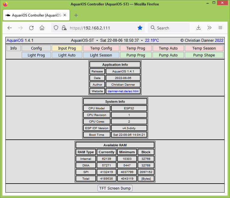
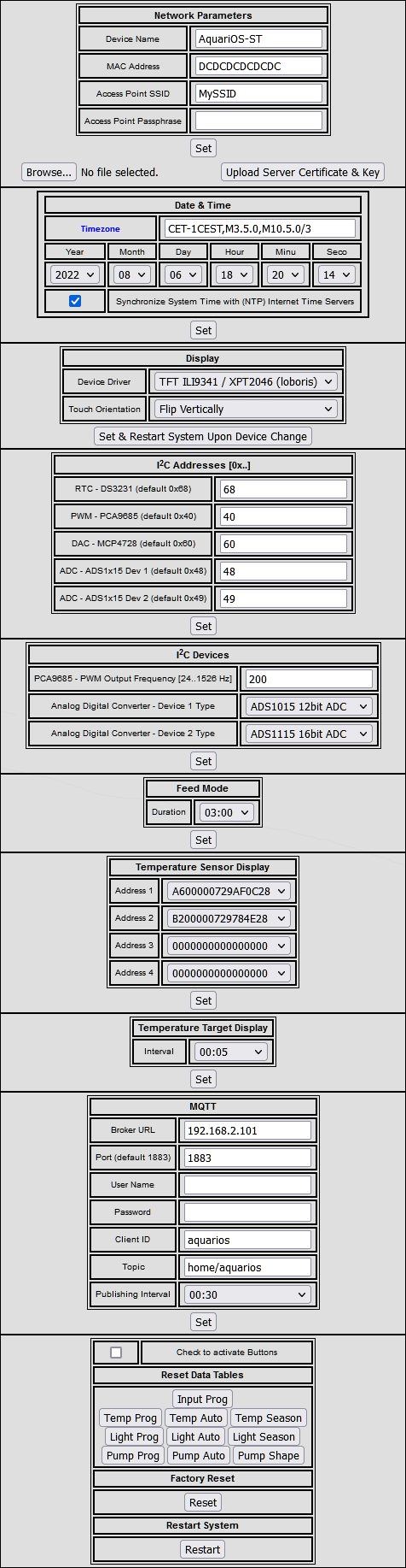
Configuration
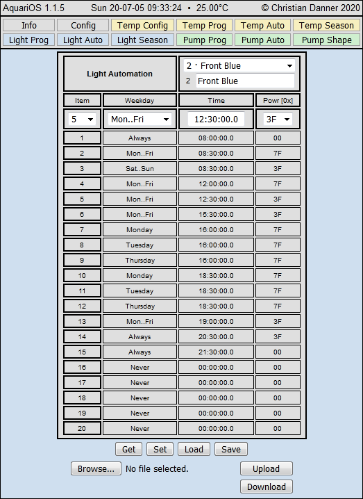
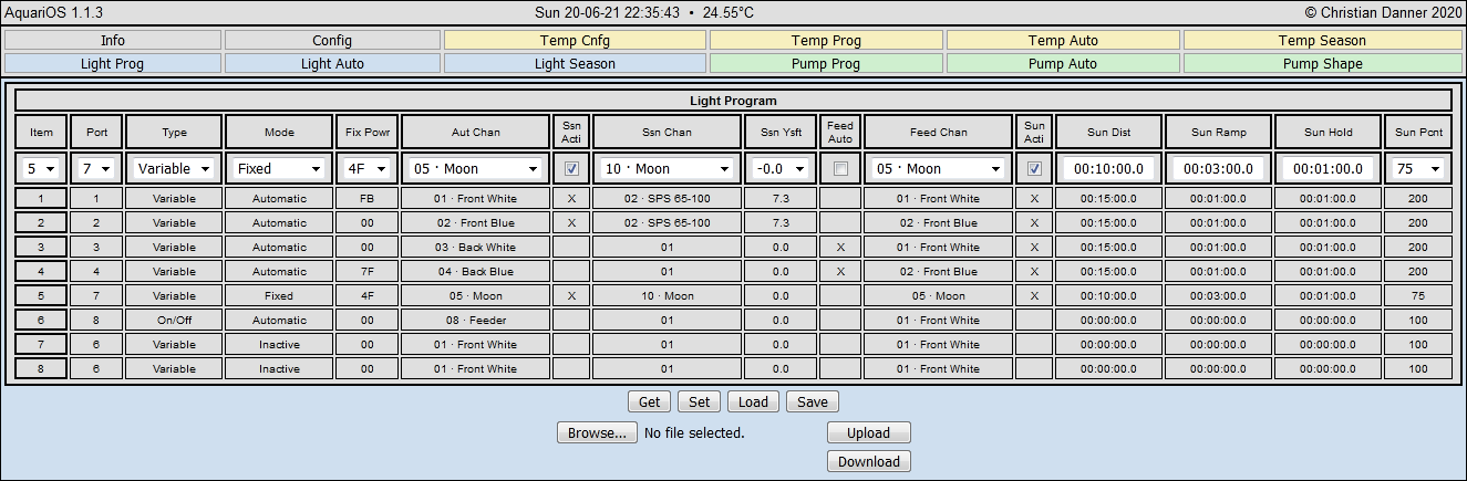
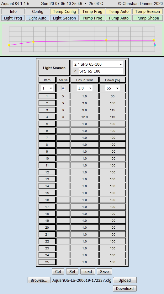
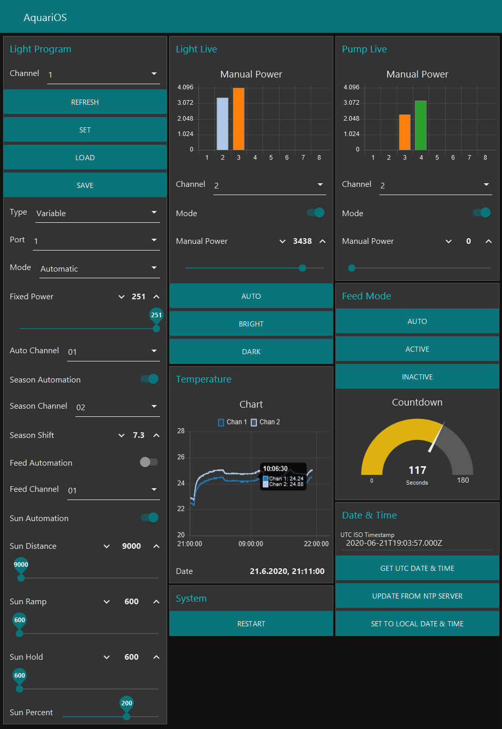
 Light
Light
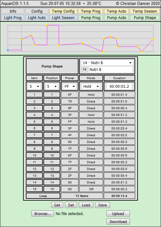
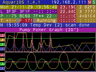
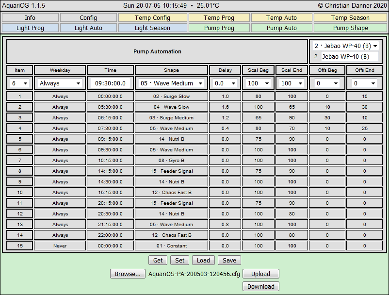
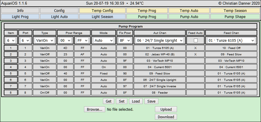
 Pump
Pump
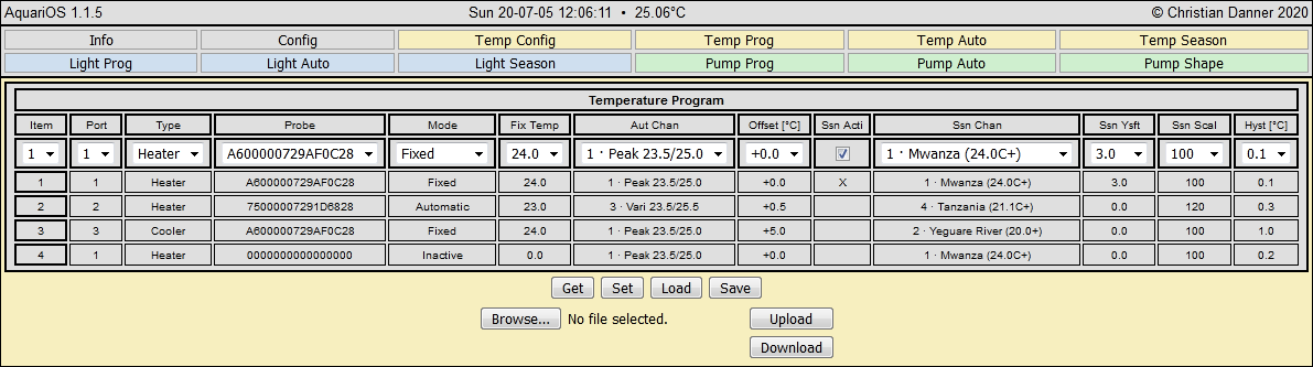
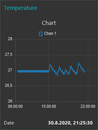
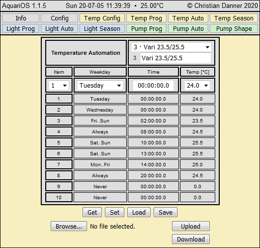
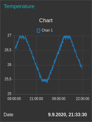
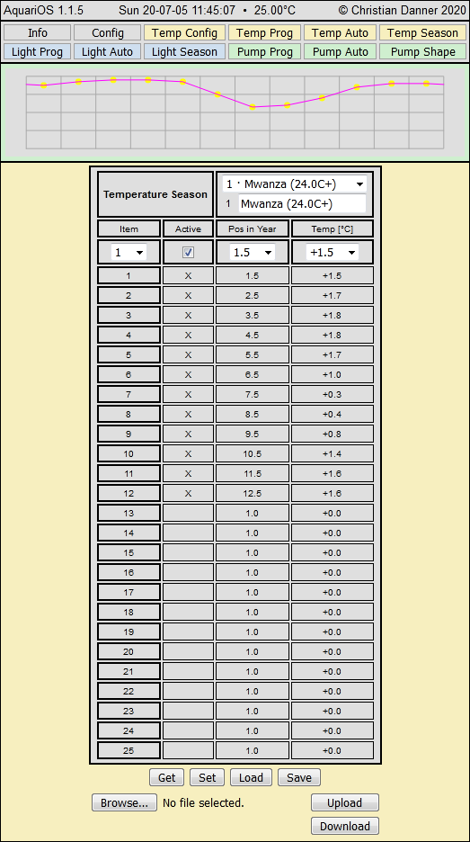
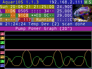
 Temperature
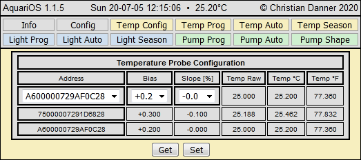
 Input
Input

 MQTT
MQTT
| Table of MQTT commands and data returned | ||||
|---|---|---|---|---|
| Direction | Topic | Payload | Description | |
| Name | Data | |||
| System | ||||
| Subscribed | sc/set | rst | Restarts AquariOS system | |
| Date & Time | ||||
| Subscribed | dc/set | cardinal [milliseconds since epoch, only seconds valid] | Sets system date & time | |
| dc/net | Induces retrieval from NTP server | |||
| dc/get | Induces dc/ret publishing | |||
| Published | dc/ret | name | Timestamp [ms since epoch (19700101 0000 UTC)] | Published system date & time |
| type | dd | |||
| valu | cardinal | |||
| Temperature | ||||
| Published | td/ret | name | Temperature [°C] | Published temperature of active probes (0..3) |
| type | td | |||
| chan | cardinal | |||
| valu | float | |||
| Input | ||||
| Published | id/ret | name | Input | Published input signal levels of active probes |
| type | id | |||
| chan | cardinal | |||
| raw | integer | |||
| adj | integer | |||
| Feed Control | ||||
| Subscribed | fc/set | [ina|act|aut] | Sets Feed Mode: ina:Inactive | act:Active | aut:Count-Down Automation | |
| Published | fc/ret | name | Feed Duration Remaining [s] | Published remaining feed duration |
| type | fd | |||
| valu | cardinal | |||
| Light Control | ||||
| Subscribed | lc/set | [aut|min|max] | Sets Light Mode: aut:Automatic | min:Minimum (Dark) | max:Maximum (Bright) | |
| Light Program | ||||
| Subscribed | lp/sav | Saves Light Program data to non-volatile RAM | ||
| lp/lod | Loads / restores Light Program data from non-volatile RAM | |||
| lp/set | chan | cardinal [0..7] | Sets Light Program dataset (item 0..7), implies 'lp/get [0..7]' | |
| mode | cardinal [0..4] | Mode: 0:Inactive | 1:Off | 2:On | 3:Fixed | 4:Auto | ||
| devi | cardinal [0..1] | Device Type: 0:On/Off | 1:Variable | ||
| port | cardinal [0..7] | Port Number [0..7] | ||
| fxpw | cardinal [0..255] | Fixed Power | ||
| auch | cardinal [0..9] | Automation Channel Number | ||
| ssac | boolean [false|true] | Seasonal Adjustment Activation Switch: false:Inactive | true:Active | ||
| ssch | cardinal [0..19] | Seasonal Adjustment Channel Number | ||
| ssys | cardinal [0..119] | Seasonal Adjustment 120th Of Year Shift | ||
| feac | boolean [false|true] | Feed Mode Activation Switch: false:Inactive | true:Active | ||
| fech | cardinal [0..9] | Feed Mode Channel Number | ||
| sact | boolean [false|true] | Sun/Cloud Simulation Activation Switch: false:Inactive | true:Active | ||
| sdst | cardinal [0..863998] | Sun/Cloud Simulation Event Distance [10th Of Seconds] | ||
| srmp | cardinal [0..863998] | Sun/Cloud Simulation Ramping Time [10th Of Seconds] | ||
| shld | cardinal [0..863998] | Sun/Cloud Simulation Holding Time [10th Of Seconds] | ||
| spct | cardinal [0..300] | Sun/Cloud Simulation Power Percentage | ||
| lp/get | cardinal [0..7] | Initiates publishing of a Light Program dataset (item 0..7) | ||
| Published | lp/ret | name | Light Program | Published Light Program dataset (item 0..7) |
| type | lp | |||
| Payload similar to 'chan' .. 'spct' described above | ||||
| Light Manual Override | ||||
| Subscribed | lm/set | chan | cardinal [0..7] | Sets Light Manual Override data (item 0..7), implies 'lm/get [0..7]' |
| mode | boolean [false|true] (optional) | Mode: false:Inactive | true:Active | ||
| powr | cardinal [0..4095] (optional) | Light Power | ||
| lm/get | cardinal [0..7] | Initiates publishing of a Light Manual dataset (item 0..7) | ||
| Published | lm/ret | name | Light Manual Override | Published Light Manual Override data (item 0..7) |
| type | lm | |||
| Payload similar to 'chan' .. 'powr' described above | ||||
| Pump Manual Override | ||||
| Subscribed | pm/set | chan | cardinal [0..7] | Sets Pump Manual Override data (item 0..7), implies 'pm/get [0..7]' |
| mode | boolean [false|true] (optional) | Mode: false:Inactive | true:Active | ||
| powr | cardinal [0..4095] (optional) | Pump Power | ||
| pm/get | cardinal [0..7] | Initiates publishing of a Pump Manual dataset (item 0..7) | ||
| Published | pm/ret | name | Pump Manual Override | Published Pump Manual Override data (item 0..7) |
| type | pm | |||
| Payload similar to 'chan' .. 'powr' described above | ||||
| Topic | dm net |
| Payload |
| Topic | home/aquarios/dm/set |
| Payload | 1582931367000 |
| Topic | home/aquarios/lp/set |
| Payload |
{ "chan": 4, "port": 4, "devi": 1, "mode": 4, "fxpw": 63, "auch": 4, "ssac": true, "ssch": 1, "ssys": 73, "feac": false, "fech": 4, "sact": true, "sdst": 6000, "srmp": 1200, "shld": 600, "spct": 75 } |
| Topic | home/aquarios/lp/ret |
| Payload |
{ "vers": "1.0", "time": 1582925077, "name": "Light Program", "type": "lp", "load": { "chan": 4, "port": 4, "devi": 1, "mode": 4, "fxpw": 63, "auch": 4, "ssac": true, "ssch": 1, "ssys": 73, "feac": false, "fech": 4, "sact": true, "sdst": 6000, "srmp": 1200, "shld": 600, "spct": 75 } } |
Support
!!! Important Notes !!!
And now ... Action!